What Is the Best Inverter Transformer for 2026?
Choosing the best Inverter Transformer for 2026 depends less on a brand name than on the system it must serve. A unit designed for a solar installation may not suit a battery inverter, industrial drive, or backup power system. Start with the inverter’s output voltage, rated power, frequency, and waveform. Then compare those details with the transformer’s kVA rating, insulation class, temperature rise, and duty cycle. Small mismatches can cause excess heat, noise, voltage drop, or early failure. No universal winner.
This guide examines the features that matter in real installations: load profile, surge demand, cooling method, isolation needs, enclosure, and available space. It also explains how to read datasheets and assess manufacturer documentation, warranty terms, and technical support. Look for clear test information and ratings that match the intended application; a polished product page alone proves little. That sounds obvious, but it is easy to overlook when specifications are scattered across documents. A transformer can be well made and still be the wrong choice. Installation conditions matter, too: a dusty equipment room or limited airflow changes what is practical. Rather than naming one model as best for every buyer, the sections ahead compare selection criteria and common trade-offs. Verify final sizing with a qualified electrical professional and the inverter manufacturer’s guidance. The right choice is the one that fits the actual load, environment, and documented requirements—not just the headline rating.
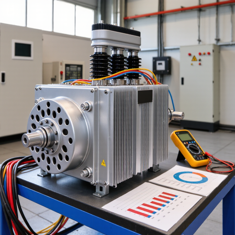
What an Inverter Transformer Is and How It Works
What Is the Best Inverter Transformer for 2026?
What an Inverter Transformer Is and How It Works
An inverter transformer transfers electrical energy between circuits through electromagnetic induction. In a solar or battery system, the inverter first changes direct current into alternating current. The transformer then adjusts the AC voltage for a building, microgrid, or utility connection. It may also provide electrical isolation, depending on the design. Think of it as a carefully sized bridge between the inverter’s output and the equipment receiving power.
Inside, alternating current in the primary winding creates a changing magnetic field in the core. That field induces voltage in the secondary winding. Inverter output can contain switching harmonics, so core material, winding design, cooling, and insulation all matter. The right choice depends on voltage, load profile, environment, and permitted temperature rise—not one headline efficiency figure. IRENA’s Renewable Capacity Statistics 2024 reports that renewables added 473 GW in 2023, representing 86% of global power capacity additions. That growth makes reliable inverter-connected equipment increasingly important, though the statistic alone cannot determine a transformer’s suitability.
Tips: Check the inverter’s output waveform and the transformer’s continuous-duty rating. Confirm harmonic and temperature limits with qualified engineering documentation. Leave space for ventilation. A unit that fits on paper may still run hotter than expected in a dusty enclosure.
What Is the Best Inverter Transformer for 2026?
How an Inverter Transformer Works
A transformer transfers AC energy between windings and changes voltage according to its turns ratio. This idealized example shows a 5:1 step-up transformer: 24 V RMS on the primary winding becomes 120 V RMS on the secondary winding at the same 60 Hz frequency. Actual inverter waveforms and output voltage depend on the inverter design and load; transformer losses are not shown.
Key Types of Inverter Transformers and Their Applications
What Is the Best Inverter Transformer for 2026?
The best inverter transformer depends on the inverter’s design, load, and required isolation. A laminated steel transformer suits many low-frequency inverters. It can provide galvanic isolation and tolerate brief surge loads, but it adds weight and takes up space. Toroidal transformers are often more compact, with low stray magnetic fields. However, their startup inrush current needs attention.
High-frequency ferrite transformers are common in compact switching designs. They can reduce size and weight, but their performance depends on switching frequency, insulation, cooling, and careful layout. An autotransformer can adjust voltage efficiently. It does not provide galvanic isolation, so it is not interchangeable with an isolated design. There is no universal winner. A neat wattage comparison can still miss motor-starting surges or heat buildup during long operation.
Tips: Check continuous and surge ratings against the actual load, not just its label. Confirm the input and output voltages, waveform compatibility, insulation requirements, and cooling method. For a refrigerator or pump, allow for startup demand. For sensitive electronics, verify output quality. Leave room for ventilation, too. Small details matter. If the application is unusual, have a qualified electrical professional review the design.
How to Compare Inverter Transformer Ratings and Features
When comparing inverter transformers, match the input and output voltages to the inverter and the equipment it will power. Check the rated frequency, too; a transformer designed for 50 Hz may not suit every 60 Hz application. Look at the VA rating, not only the advertised wattage. Motors and compressors can draw a brief surge when starting, so allow headroom for that demand. A close fit on paper may still trip in practice.
Check whether the transformer supports the inverter’s output waveform. Modified-wave outputs can cause extra heat or noise in some transformer designs. Pure sine wave compatibility is often a safer choice for sensitive equipment, but confirm the specifications rather than assuming. Efficiency matters as well: losses become noticeable as heat during long operating periods. Watch the temperature rating and duty cycle. Heat adds up.
Construction details deserve attention. Compare insulation, cooling method, terminal protection, and whether the unit provides electrical isolation. Verify the rated load against your real operating conditions, including ambient temperature and ventilation. A neat spec sheet can still leave questions about startup surges or continuous use. Ask for test data when the application is demanding, and treat unexplained gaps as a reason to investigate further.
Factors to Consider When Choosing an Inverter Transformer in 2026
What Is the Best Inverter Transformer for 2026?
Factors to Consider When Choosing an Inverter Transformer in 2026
Choosing an inverter transformer starts with the equipment it must power. List each load, its operating voltage, and its rated wattage. Then check the inverter’s continuous output and short-duration surge capacity. Motors, pumps, and compressors can draw several times their normal current at startup. Surge matters. A unit that matches the total running wattage may still trip when a motor starts.
Check waveform and frequency compatibility, especially for sensitive electronics or medical and control equipment. A pure sine-wave output is generally a safer match for devices designed for standard utility power, but verify each device’s specifications. Confirm that the transformer’s input voltage suits the battery or inverter system. Mismatched voltage can cause poor performance, overheating, or damage. The details on a label can be easy to overlook.
Heat and installation conditions matter, too. A transformer in a cramped cabinet may run hotter than one in a ventilated space. Review temperature limits, cooling requirements, insulation, and protection against dust or moisture. Efficiency affects wasted energy and heat, but compare figures measured under similar conditions. Ask for clear test data and applicable safety documentation. In complex installations, have a qualified technician check cable sizing, grounding, and compatibility; a neat calculation is not a substitute for inspecting the actual setup.
Matching an Inverter Transformer to Your System and Operating Needs
What is the best inverter transformer for 2026? It is the one matched to your inverter’s actual AC output, site conditions, and operating profile—not simply the largest unit available. Check the inverter’s continuous power, output voltage, permitted overload, and expected operating hours. Then confirm the transformer’s kVA rating, impedance, cooling method, and temperature limits. Easy to overlook: a transformer that looks adequate on a nameplate may need derating in a hot enclosure or at altitude.
NREL’s 2024 Annual Technology Baseline uses a 1.34 inverter loading ratio for utility-scale solar, comparing DC array capacity with inverter AC capacity. That ratio is not a transformer-sizing formula. It does show why DC panel capacity alone can mislead; base transformer selection on the AC side and the system’s simultaneous output. Include harmonic performance and future expansion, too. I would check those assumptions twice.
Efficiency deserves attention alongside fit. The U.S. Department of Energy’s 2024 distribution-transformer standards analysis projects 10.3 quadrillion Btu in cumulative energy savings over 30 years across covered equipment. That scale makes no-load and load losses worth comparing over the expected duty cycle, not just at peak output. Ask for test data at relevant loading levels, and verify grid voltage and protection requirements with the project engineer. A tidy spreadsheet can still miss a real operating condition.